Lets rebuild the display...
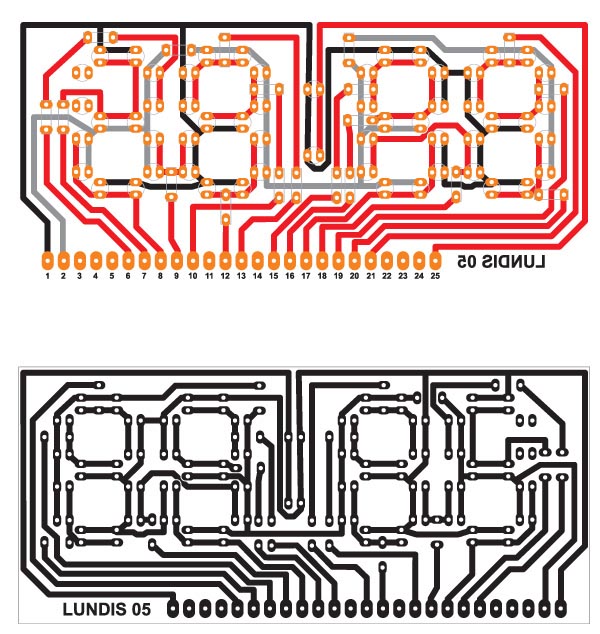
After some measuring and figeting around I came up with the following
design.
If you want to make your own clock, here's a PDF
with the circuit board design.
There's a printed circuit board primer available at Tom's
Hardware.
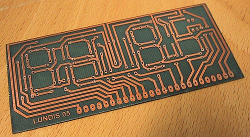
Print the PDF on OverHead film at 100%.
Mount the OverHead film (with the all black design) on the copper side
of the circuit board.
Expose the photoresist with the UV lamp.
Develop the circuit board and etch the copper.
Now, drill the holes in the PCB with a 0.6 mm drill bit. Really easy using
a Dremel multi-tool.
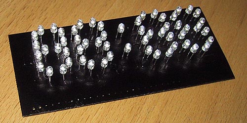
Solder all the LEDs onto the PCB with the cathode (-) of the LED inserted
into the red
markingsin
the illustration. (Yeah, I know, it should be the other way around...)
Paint the side of the PCB with the LEDs black, so it won't show through
the holes in the front of the G5 case.
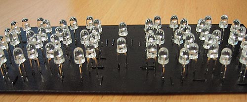
Solder all the leads, connected to the remains of the alarm clock, onto
your LED PCB.